
e-Powertrain expertise
Over the past 10 years, we have significantly expanded our capabilities in the realm of e-powertrain design. Our dedication to innovation has led us to develop highly reliable models for various types of vehicles, both on and off-highway. This expertise positions us at the forefront of the transition to electric mobility, ensuring our clients stay ahead of the curve.

Balancing Conflicting Requirements
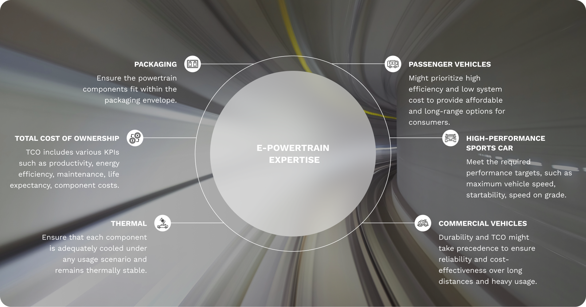
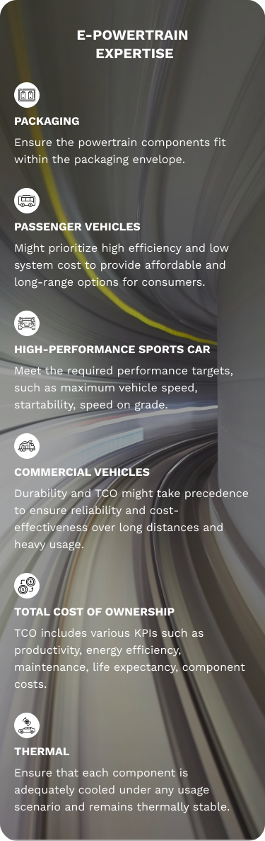
Key Design Decisions in
e-Powertrain Development
Key Design Decisions in
e-Powertrain Development
Architecture (Mechanical)
Engibex has in-house models to simulate these architecture combinations, for static requirements & for dynamic cycle simulation for energy efficiency, performance & therma.
• Number of motors
• Gearbox for each motors
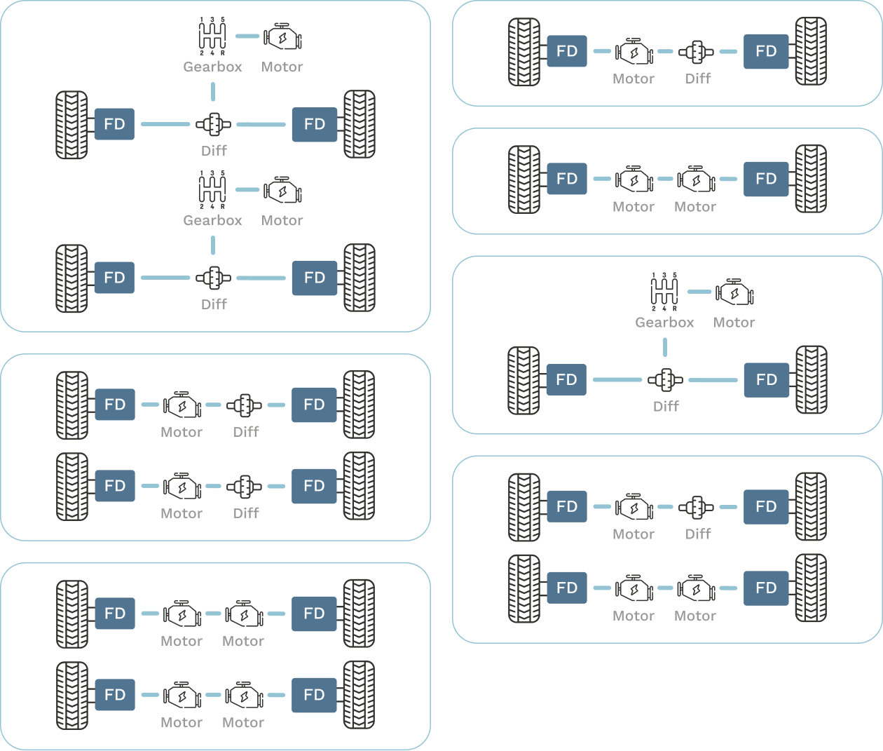
Whether it be an BEV or HEV, the architecture of the powertrain is foundational decision. How many motors, fixed ratio or shift gearbox, FWD or RWD or AWD, whether to have 2 in-wheel motor RWD that allows torque-vectoring enhancing vehicle dynamics or go for all 4-in-wheel motors... these are just some of the questions necessary to answer at the early stage of the design.
Architecture (Electrical)
Engibex has in-house models and methodology for sizing optimization for component & system to meet requirements and maximize efficiency.
Battery Life and Fuel Cell life are modeled for product lifetime TCO optimization, including optimal energy management
• DC Voltage level: 24V/ 48V / 350V / 400V / 800V / 1000V / ...
• DC/DC or not
• BEV or Hybrid
• Fuel-Cell Hybrid or Diesel-Engine hybrid
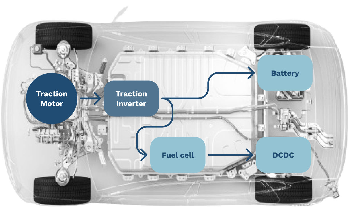
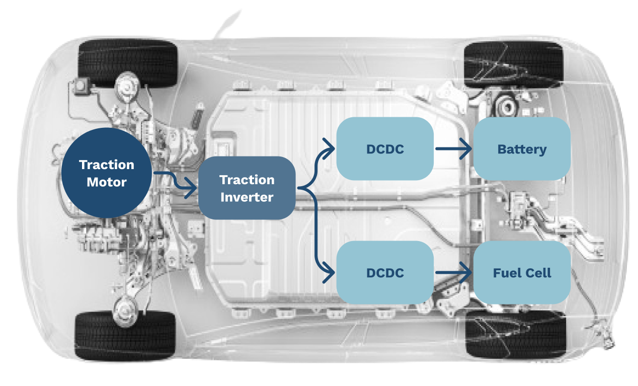
Key design decisions for electrical architectures like the bus voltage level directly affects the fast charging capability and the powertrain performance. Other decisions like having a DCDC converter to stabilize the bus voltage, having multiple battery or battery+super-cap hybrid or battery+Fuel Cell hybrid etc ensure the autonomy and efficiency of the vehicle.
Energy Storage
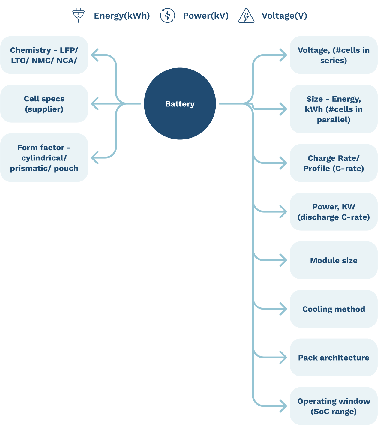
Battery is, in most cases, the bottleneck for increasing the autonomy/range and reducing the system cost of a BEV. It becomes paramount to select the right battery chemistry, right cell type, cell supplier, module and pack configuration, cooling design and charging strategy to get the optimized system under the cost target.
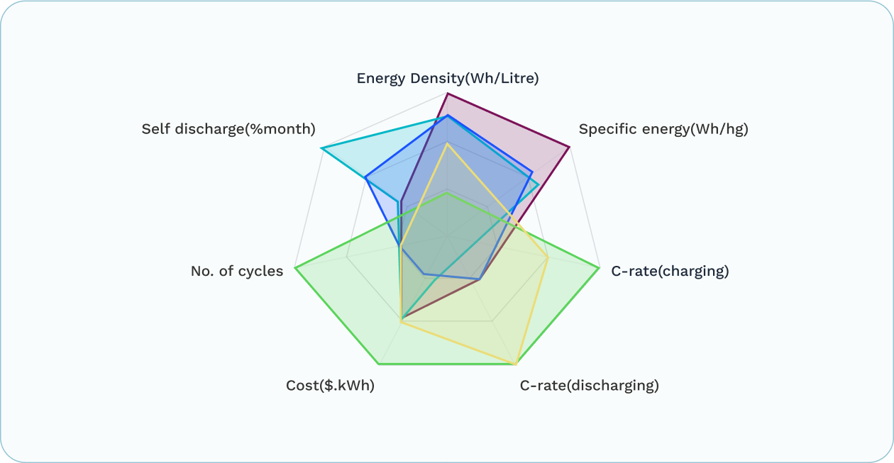
Engibex has in-house models and methodology for:
• Cell selection & comparison
• Pack sizing
• Cell 2 module 2 pack thermal evaluation
• Cell model (ECM) identification
• Design optimization of cooling concepts
• Rate to maximize TCO Optimize charge (considering battery ageing)
Motor Design
Design and selection of electric motor involves multi-facet problem solving involving electrical, electromagnetic, mechanical strength, thermal - fluid engineering, NVH, material science and manufacturing technology. Variety of motor technology and large variation of associated design variables make finding the correct design even more challenging.
Axial Flux vs Radial Flux
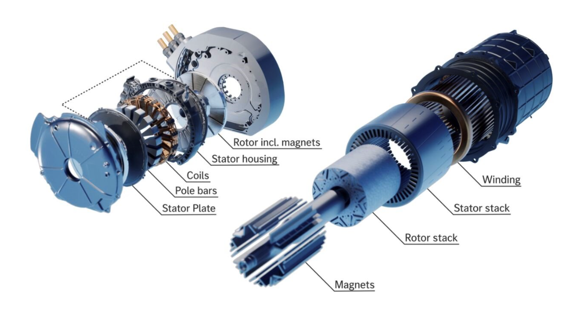
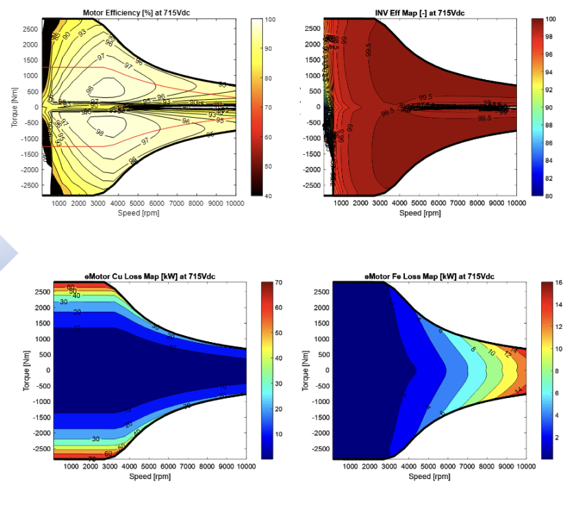
Engibex has in-house motor SCALABLE models and methodology enabling:
- Cell selection & comparison
- Pack sizing;
- Motor design selection (technology, cross section topology,
all design parameters - length, Dia, ...) - Cooling design evaluation - water jacket vs oil vs combined;
- Optimal Inverter (power module) selection.

These are some of the examples of outputs from scalable models
(54Q5_6p, OD350, L258, 18Turns, 715Vdc)
e-Gear Box Design
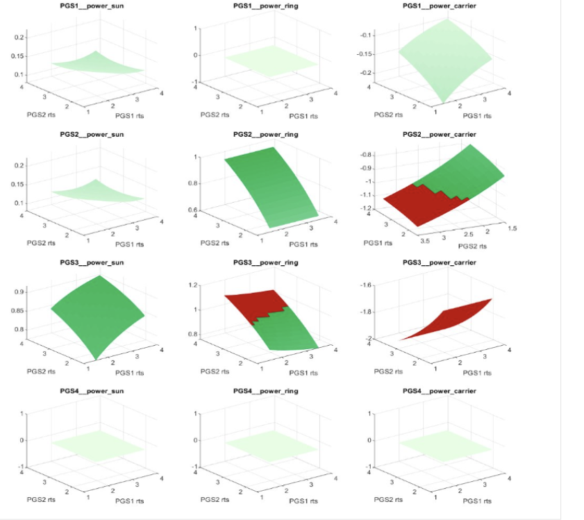
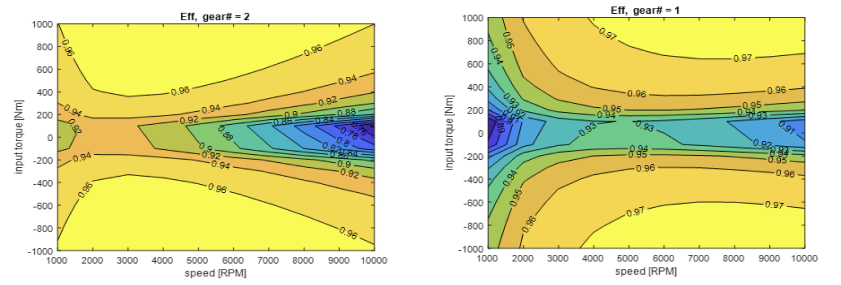
Leveraging our in-house transmission modeling and optimization tools, Engibex can analyze power recirculation, optimize packaging dimensions, weight and efficiency for given requirements. This is crucial enabler for complete powertrain optimization.
Analysis of complex architectures
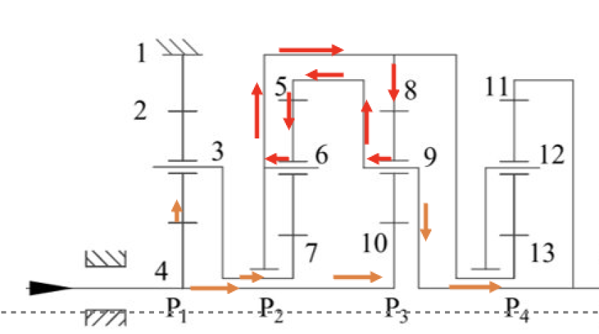
Power Recirculation detection
Efficiency estimation
DC/DC & Charger
Engibex has in-house models capabilities:
• Isolated & non-isolated converter design
• Power module selection
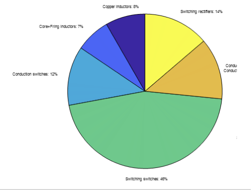
• Efficiency/ Loss modeling
• Thermal stability analysis
• Power Inductor design
• Power Transformer design
• Modular converters design

Optimal Supervisory Control
Engibex has in-house implementation of Optimal energy management methods e.g., Dynamic Programming, MPC, ECMS etc. in conjunction with Health Conscious Supervisory control & Energy Management.
