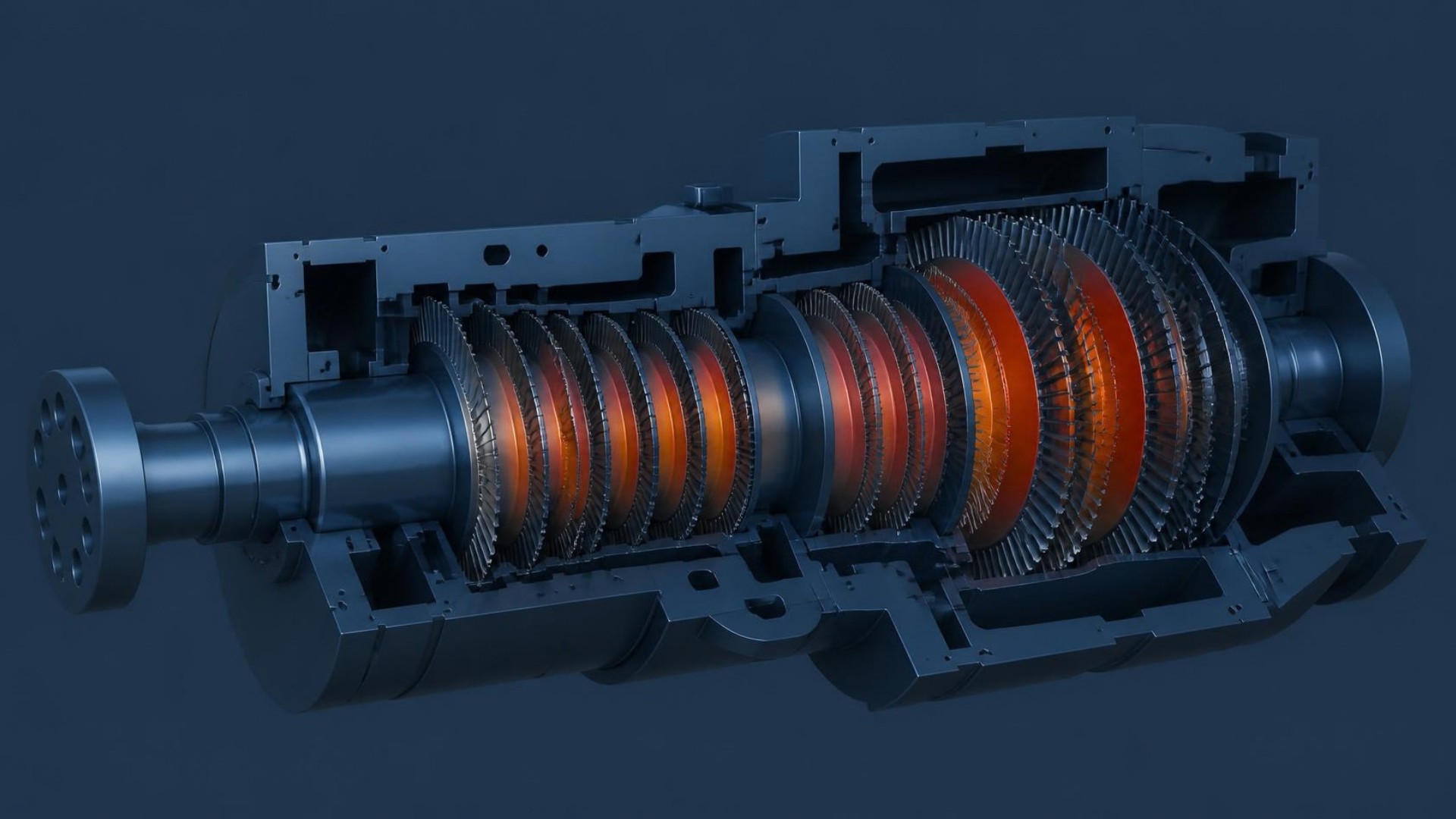
Estimating Steam Turbine Rotor Fatigue Life Under Flexible Operation: A Thermo-Mechanical FEA Workflow
Translating plant operating data into transient stresses, fatigue damage, and a defensible remaining-life estimate for steam turbine rotors exposed to more frequent startups and shutdowns.
Abstract
As power grids absorb more variable renewable generation, thermal power plants are increasingly required to load-follow, shut down and restart — exposing steam turbine rotors to more frequent thermal transients and cyclic thermo-mechanical stresses. This article describes a thermo-mechanical finite element (FE) workflow that reconstructs the thermal loading experienced by a rotor from plant operating data, translates it into local stresses and strains, and estimates the resulting low-cycle-fatigue damage and remaining lifetime. It closes by examining the main sources of uncertainty in such an assessment, and why a defensible estimate should be expressed as a range rather than a single number.
Introduction
The transition toward a more renewable electricity mix is fundamentally changing the way conventional thermal power plants are operated. As solar and wind generation increase, the electricity grid experiences larger variations between periods of high renewable production and periods when additional dispatchable generation is required. Thermal power plants that were traditionally operated close to a steady baseload are therefore increasingly required to load-follow, shut down, and restart. For example, during periods of high solar generation, a thermal power plant may be taken offline to balance the grid, before being brought back into service when electricity demand exceeds renewable production. Each startup and shutdown exposes critical turbine components to rapid temperature changes and associated thermal gradients. In thick and highly constrained components such as steam turbine rotors, these transients generate significant cyclic thermo-mechanical stresses that can accelerate fatigue damage. Research on flexible turbine operation has indeed shown that the increased frequency of startups and the associated thermal transients can significantly influence the fatigue behaviour of high-temperature rotor components.
Steam turbine rotor cracking is not a new failure mechanism: low-cycle fatigue caused by transient thermal stresses during startups and shutdowns has been recognized for decades. What has changed is the operating regime of many plants. Increasingly frequent and faster thermal transients mean that rotors originally designed for relatively stable baseload operation may accumulate fatigue damage more rapidly than anticipated. During a startup or shutdown, the rotor does not heat up or cool down uniformly. Temperature differences develop between its surface and core, while geometric features such as grooves, fillets, bores and other stress concentrations locally amplify the resulting stresses. When these stresses repeatedly drive the material into the elastic-plastic regime, cyclic strain accumulates and can eventually initiate a crack. In simple terms, elastic deformation is recoverable when the load is removed, whereas plastic deformation leaves a permanent change in shape. This makes low-cycle fatigue and, depending on temperature and operating conditions, coupled creep-fatigue behaviour important mechanisms to consider when assessing rotor integrity.
Steam turbine rotors are therefore critical assets from both an engineering and an economic perspective. A rotor failure can result not only in extensive component damage and a costly repair or replacement, but also in prolonged turbine unavailability and significant loss of power generation. The challenge is consequently not simply to detect a crack once it has formed, but to estimate where and when critical fatigue damage is likely to develop. This is where sophisticated thermo-mechanical finite element analysis (FEA) can provide valuable insight. By reproducing the transient temperature fields, mechanical loading, local stress and strain concentrations, and the evolution of these quantities over repeated operating histories, a detailed numerical model can be used to identify critical regions and quantify their fatigue exposure. Such an assessment can support proactive decisions, including adapting startup and shutdown procedures, optimizing operating conditions, and focusing inspection or vibration-monitoring activities where they can have the greatest impact on reducing the risk of rotor failure.
From Plant Operating Data to Thermal Boundary Conditions
The first step in a reliable thermo-mechanical assessment is to reproduce as accurately as possible the thermal environment experienced by the rotor during operation. This requires determining how the steam temperature and pressure evolve throughout the different stages of the turbine and, consequently, how heat is transferred between the steam and the rotor surface.
In a turbine, the rotor surface is exposed to different flow and geometric configurations. Examples include labyrinth seals between the rotor and stationary components, rotating discs and blades, parallel rotating discs, and relatively exposed rotating surfaces. The heat transfer coefficient (HTC) is therefore not necessarily the same across the entire rotor. For each type of surface, an appropriate empirical correlation can be used to relate the HTC to dimensionless flow parameters such as the Reynolds (Re) and Prandtl (Pr) numbers through the Nusselt (Nu) number.
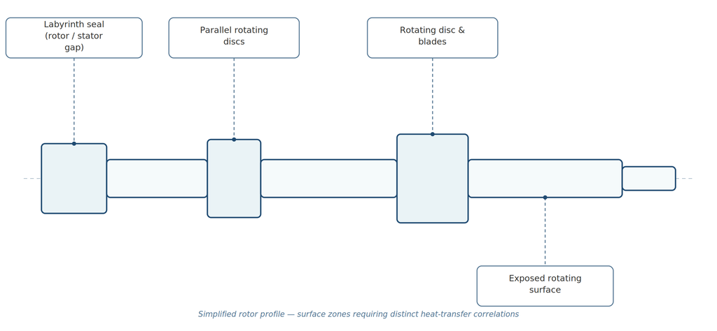
Fig. 1 — Simplified rotor profile illustrating the different surface zones, each requiring its own heat-transfer correlation.
The HTC depends on several factors, including the local rotor diameter and geometry, rotor speed, and the thermodynamic properties of the steam. These steam properties — such as density, pressure and temperature — are determined from the thermodynamic state of the steam at each turbine region. Starting from measured inlet and exhaust conditions, a thermodynamic model can be used to estimate the conditions at the intermediate turbine stages, taking into account appropriate assumptions regarding pressure drops, temperature changes and heat losses.
The required operating data are generally available from the plant's instrumentation and control systems. Steam pressure and temperature are typically measured at several locations and recorded throughout the plant's operating history. These historical data provide an important basis for reconstructing the thermal loading experienced by the rotor, particularly during startup and shutdown events.
From Thermal Loading to Thermo-Mechanical Stresses
Once the thermal boundary conditions have been established, the next step is to reproduce the transient temperature distribution within the rotor. This requires a transient thermal finite element analysis, in which heat conduction through the rotor material is calculated while the convective heat transfer at the different rotor surfaces is imposed through the corresponding HTC and steam temperature. The result is the spatio-temporal evolution of temperature throughout the rotor during a startup, shutdown, or other relevant operating transient.
The accuracy of this calculation depends strongly on how the physical model is constructed. The rotor geometry should reproduce the features that can influence the local temperature, stress and strain fields, with particular attention to geometrical discontinuities such as fillets, grooves, bores and other regions where stress concentrations may occur. At the same time, modelling every geometrical detail across the entire rotor is not necessarily beneficial. Regions sufficiently far from the locations of interest can often be represented with a lower level of geometric detail, reducing computational cost without materially affecting the results at the critical locations. The objective is therefore to achieve the appropriate level of geometric fidelity where it matters most.
The rotor material properties are another important input. Properties such as density, thermal conductivity, coefficient of thermal expansion and Young's modulus influence the calculated temperature and stress fields. Because the rotor experiences a significant temperature range during operation, these properties should generally be treated as temperature-dependent rather than constant values.
The transient temperature field obtained from the thermal analysis is then transferred to a structural finite element model. The structural analysis combines the effects of thermal expansion with the mechanical loads acting on the rotating rotor, including centrifugal loading associated with rotor speed and, where relevant, pressure, torque, bending and other operational loads. Thermal expansion is constrained by the rotor's geometry and by the interaction between different parts of the component, causing thermo-mechanical stresses to develop. The resulting local stress and strain histories can then be examined to identify the locations and operating conditions associated with the highest fatigue loading.
From Thermo-Mechanical Stresses to Fatigue Lifetime
The final step is to translate the calculated thermo-mechanical loading into an estimate of fatigue damage. For each relevant operating transient, the local stress and strain histories at the critical locations are extracted from the structural analysis. The resulting local stress-strain history is then used as input to an appropriate low-cycle-fatigue (LCF) assessment method. Depending on the methodology, quantities such as strain amplitude, stress amplitude, mean stress and the complete local stress-strain response may be required.
The principle is illustrated by considering a typical shutdown followed by a startup. During shutdown, the rotor surface may cool more rapidly than its interior, producing a temperature gradient and associated thermal stresses. During the subsequent startup, the temperature gradient reverses or evolves in the opposite direction. Repeated thermal transients therefore produce cyclic stress and strain at critical locations. An LCF model can relate this cyclic loading to the number of cycles that the material can withstand before fatigue damage reaches a defined criterion.
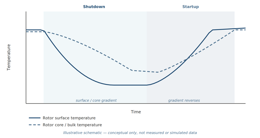
Fig. 2 — Illustrative schematic of rotor surface and core temperature during a shutdown–startup cycle, showing the reversal of the thermal gradient.
The same procedure can then be applied to the complete operating history of a specific rotor. Instead of assuming a generic number of annual startups and shutdowns, the analysis can use the actual recorded operating history to reconstruct the loading associated with individual operating transients. The resulting stress and strain history can then be processed to identify the fatigue cycles within that history, including partial or non-ideal cycles where relevant. The fatigue damage calculated for the identified cycles can subsequently be accumulated using an appropriate cumulative-damage approach. This provides an estimate of the rotor's consumed fatigue life and, importantly, allows the assessment to be updated as additional operating history becomes available.
The overall workflow can therefore be summarized as a chain running from plant operating history through to a cumulative lifetime-consumption estimate, as illustrated below.
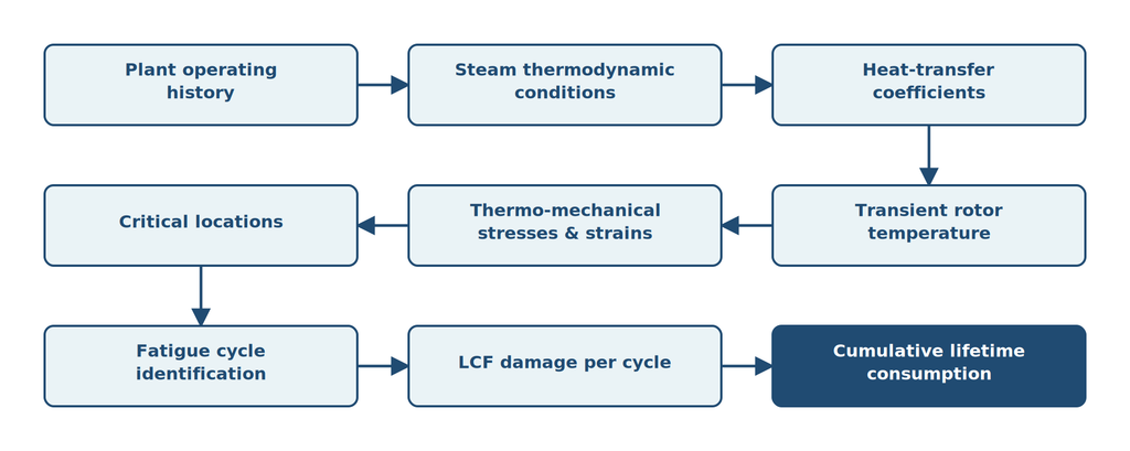
Fig. 3 — Overall workflow, from plant operating history to cumulative fatigue-life consumption.
This chain is important because the final lifetime estimate is only as reliable as the preceding steps. In particular, accurately representing the actual operating transients and the resulting thermal gradients is essential when the objective is to assess fatigue damage in a rotor subjected to repeated startups and shutdowns.
Understanding the Sources of Uncertainty
A thermo-mechanical simulation can provide a powerful framework for estimating fatigue damage and lifetime consumption of a steam turbine rotor. However, the result should not be interpreted as an exact prediction. The final lifetime estimate is the outcome of a chain of measurements, models, assumptions and approximations, each of which can introduce uncertainty or model-form error. Understanding these sources is particularly important when the objective is to make decisions about the remaining life of a critical component. It also helps identify where additional measurements, more detailed modelling or calibration can provide the greatest improvement in confidence.
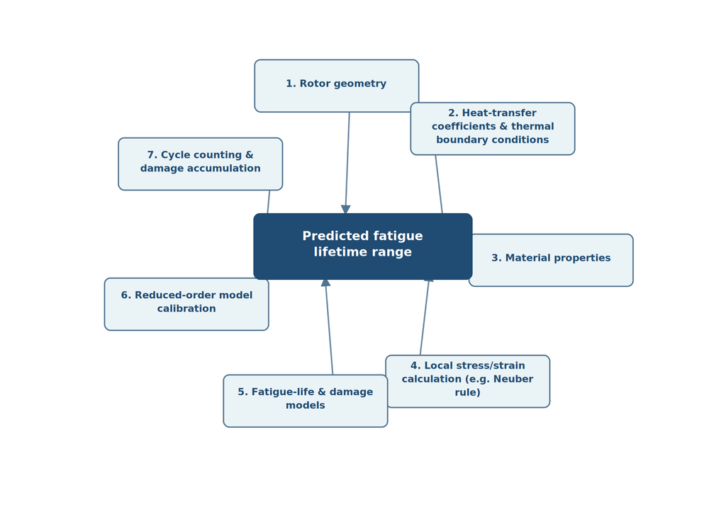
Fig. 4 — The seven main sources of uncertainty feeding into the predicted fatigue lifetime range.
1. Uncertainty in Rotor Geometry
An accurate representation of the rotor geometry is particularly important around regions where high stresses and strains are expected. In practice, however, the detailed geometry of an existing rotor is not always available. Original OEM drawings may contain insufficient detail for an independent assessment, or detailed design information may not be accessible because of intellectual-property restrictions.
A simplified geometry can therefore be reconstructed from the available drawings and dimensional information. While this may be sufficient for regions away from the critical location, even small geometric differences can significantly affect local stress and strain concentrations at features such as grooves, fillets, bores or other geometrical discontinuities. The uncertainty in geometry can consequently translate directly into uncertainty in the predicted fatigue loading.
Where access to the component is possible, reverse-engineering or replication techniques can be used to improve the geometric representation of the most critical regions. For example, an impression or molding technique can provide information about the actual shape of an inaccessible or difficult-to-measure surface. This information can then be incorporated into the FE model, improving the representation of the local stress concentration.
2. Uncertainty in Heat-Transfer Coefficients and Thermal Boundary Conditions
The calculated rotor temperature field is highly dependent on how heat is transferred between the steam and the rotor. For the different rotor surface configurations, several correlations are available in the literature for estimating the heat-transfer coefficient (HTC). These correlations are generally derived from experimental data, analytical approaches or more sophisticated CFD simulations and are applicable within particular ranges of geometry and operating conditions.
Consequently, selecting an HTC correlation introduces uncertainty into the thermal model. Different correlations may produce different HTC values for the same nominal operating conditions, and their relative accuracy may depend on the specific geometry and flow regime of the rotor. The accuracy of the HTC calculation can therefore influence the predicted rotor temperature and thermal stress.
The uncertainty is further increased by uncertainty in the actual steam conditions at the rotor surface. Plant instrumentation provides valuable measurements of pressure and temperature, but the measured quantities are not necessarily available at every location required by the model. Intermediate stage conditions therefore need to be reconstructed using a thermodynamic model and assumptions concerning pressure drops, heat losses and other effects. Measurement uncertainty and model assumptions consequently propagate into the calculated thermal boundary conditions.
3. Uncertainty in Material Properties
The thermo-mechanical model also requires temperature-dependent material properties, including density, thermal conductivity, coefficient of thermal expansion, Young's modulus and, when plasticity or creep is considered, appropriate constitutive and cyclic material parameters.
Complete temperature-dependent datasets are not necessarily available for every rotor alloy. Material properties may instead be obtained from handbooks, published literature or experimental data available at selected temperatures, with interpolation used between measurement points and, where necessary, extrapolation beyond them.
There is an additional challenge when assessing an in-service rotor. The actual material condition may differ from that represented by standard material-property data because of manufacturing history, heat treatment, long-term exposure to elevated temperature, thermal aging or other service effects. These differences can introduce further uncertainty into the predicted stress-strain response and fatigue life.
4. Uncertainty in Local Stress and Strain Calculation
A detailed elastic-plastic thermo-mechanical FE analysis would provide the most direct representation of the local stress and strain response, but it can be computationally demanding. For practical engineering assessments, a linear-elastic FE analysis is therefore often used to calculate the global thermo-mechanical response, followed by a correction method to estimate the local elastic-plastic response at critical stress concentrations.
One commonly used approach is the Neuber rule, which relates the elastic solution to an estimated local elastic-plastic stress and strain state. Such approaches have been applied to steam-turbine rotor grooves and can provide useful estimates of local strain amplitudes.
However, this simplification has limitations. A conventional Neuber correction does not by itself reproduce the full history-dependent material response, including cyclic plasticity, creep deformation and stress relaxation during high-temperature operation. For example, after a rotor reaches nominal operating conditions following a startup, local stresses can relax through creep and plastic deformation. The resulting stress-strain state depends on the preceding thermal and mechanical history. If this history dependence is not explicitly modelled, additional uncertainty is introduced into the calculated fatigue loading.
5. Uncertainty in Fatigue-Life and Damage Models
The calculated stress and strain history must ultimately be converted into fatigue damage using an appropriate low-cycle-fatigue model. This step introduces another important source of uncertainty.
Strain-life or LCF curves are generally derived under controlled laboratory conditions and do not necessarily reproduce all aspects of the complex thermo-mechanical history experienced by an operating rotor. In particular, the stress-strain cycle in a rotor may not be symmetric, and the local material state may contain residual stresses and strains resulting from previous plastic deformation and high-temperature stress relaxation.
Consequently, simply applying a conventional LCF curve to the strain range may not fully represent effects such as mean stress, residual stress, cyclic plasticity or creep-fatigue interaction. These effects can become particularly relevant for components operating at elevated temperature and subjected to repeated startup and shutdown cycles. More sophisticated approaches can incorporate the actual stress-strain history and, where required, account explicitly for creep and fatigue interaction.
6. Computational Cost and the Need for Reduced-Order Models
There is also a practical limitation associated with the computational cost of detailed FE simulations. During a startup or shutdown, the temperature within a rotor can change rapidly, requiring sufficiently fine time resolution to capture the thermal gradients that drive the local stresses. At the same time, the operating history of an existing turbine may extend over many years and contain hundreds or thousands of individual operating transients.
Running a detailed thermo-mechanical FE model for every time increment of the entire operating history can therefore become computationally impractical. This motivates the development of reduced-order or surrogate models that reproduce the response of the more detailed FE model at a fraction of the computational cost. Such approaches have been investigated specifically for steam-turbine rotor fatigue-life monitoring because full nonlinear FE calculations become impractical when long stress histories need to be processed.
A simplified one-dimensional model, for example, can provide a rapid estimate of the thermal and mechanical response at the critical location. However, reducing the dimensionality inevitably requires simplifications. Axial effects and other three-dimensional phenomena may be neglected, and the reduced-order model therefore needs to be calibrated against results from a more detailed FE model. The calibration itself introduces another source of uncertainty, particularly if the operating conditions extend beyond those represented during calibration.
7. Uncertainty in Cycle Counting and Damage Accumulation
Once the strain history has been reconstructed over the complete operating history, cycle-counting methods such as the rainflow algorithm can be used to identify individual fatigue cycles and their associated strain ranges. The calculated cycles are then combined with the selected fatigue-life model to determine the damage associated with each cycle.
A common engineering assumption is that the damage from individual cycles can be treated independently and accumulated linearly. Under this assumption, the total fatigue damage is obtained by summing the damage fractions associated with all identified cycles, consistent with the classical Palmgren-Miner approach. This provides a practical way of converting a complex operating history into a cumulative fatigue-damage estimate.
However, linear damage accumulation is itself an approximation. The damage produced by one cycle can depend on the preceding loading history, and interactions between fatigue, creep, plasticity and stress relaxation can cause the actual damage accumulation to deviate from a simple linear sum. Consequently, the choice of damage-accumulation model represents a further source of uncertainty in the final lifetime estimate.
From a Single Lifetime Estimate to a Range of Possible Outcomes
These sources of uncertainty illustrate an important point about thermo-mechanical lifetime assessment: the sophistication of the FE model should not be confused with certainty in the final prediction. Uncertainty can enter through the geometry, thermal boundary conditions, material properties, constitutive model, fatigue data, reduced-order model and damage-accumulation method.
For this reason, a robust assessment should ideally go beyond reporting a single predicted lifetime. Sensitivity and uncertainty analyses can be used to determine which input parameters have the greatest influence on the result and, where sufficient information is available, to quantify a range of possible fatigue damage or remaining life. This provides a more transparent basis for engineering decisions and helps identify where additional measurements or inspection data could most effectively reduce uncertainty.
Discussion
A few practical implications follow from this workflow for plant operators and asset managers considering a similar assessment:
- Treat the rotor as a system, not a single hot spot. Geometry, thermal boundary conditions, material data and the fatigue model all interact — improving one input in isolation rarely improves confidence in the final estimate as much as addressing the weakest link in the chain.
- Use the plant's own operating history. A generic assumption of annual startups and shutdowns is far less informative than reconstructing the loading from actual recorded operating data, and it allows the assessment to be updated as new history accumulates.
- Ask for a range, not a single number. A single predicted remaining life can be misleading given the sources of uncertainty involved; a sensitivity or uncertainty analysis gives a more defensible basis for maintenance and inspection decisions.
- Target inspection and monitoring where they matter most. Once critical locations and their dominant uncertainty sources are identified, inspection and vibration-monitoring effort can be focused where it will most effectively reduce risk, rather than spread evenly across the rotor.
Conclusion
As thermal power plants increasingly operate in a flexible mode to complement variable renewable generation, steam turbine rotors are exposed to more frequent and demanding thermal cycles, making fatigue damage an increasingly important consideration for asset integrity. Thermo-mechanical FEA provides a powerful framework for translating actual operating conditions into transient temperature fields, local stresses and strains, and ultimately estimates of fatigue damage and lifetime consumption. However, the reliability of such an assessment depends not only on the sophistication of the FE model, but also on the quality of the geometry, thermal boundary conditions, material data, fatigue models and assumptions used to process long-term operating histories. Recognizing and quantifying these sources of uncertainty is therefore essential. When combined with plant operating data, appropriate reduced-order models, and targeted inspection and monitoring strategies, thermo-mechanical simulation can provide a valuable basis for proactive rotor integrity management — helping plant operators make informed decisions before accumulated fatigue damage reaches a critical level.